Heatmaps
Use a single colour overlay to keep a mould diagnostic beside the design controls, or open the Heatmaps workspace to compare two or three fields over the same live sail and camera view.
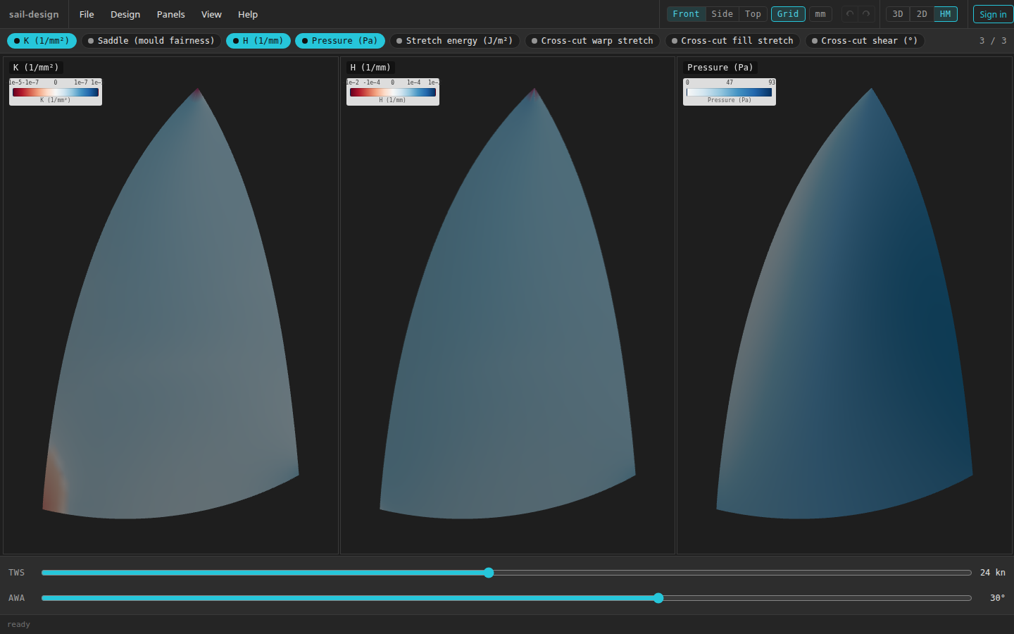
This controlled Albin Vega 27 gennaker example compares K, H, and Pressure at TWS 24 kn and AWA 30°.
- Eight-entry picker; three selected
- Legend for each field
- Three tiles sharing one camera
- Wind controls for the selected Pressure field
Choose the inspection surface
The app exposes heatmaps in two distinct places. Their selections are saved separately as local browser preferences; neither changes the sail or becomes part of the design file.
| Surface | What it is for | Current choices | State when you return |
|---|---|---|---|
| Preview/Profile overlay | Keep one field on the normal 3-D mould beside the Shape controls | None, K, Saddle, or H | The one selected field is remembered |
| HM workspace | Compare two or three fields side by side | All eight current entries | The selected chips are remembered; camera and wind restart |
Show one field while editing
Open Preview or Profile Edit
Click 3D, then choose Preview or Profile Edit in the Shape card. The selector is deliberately absent from Colours, where panel colours own the surface.
Choose a Heatmap
In the Shape card's View section, choose K (1/mm²), Saddle (mould fairness), or H (1/mm) from Heatmap. The default is None.
The selected field replaces the cloth skin on the smooth surface and adds its legend near the bottom of the viewport. Choosing None restores the selected skin.
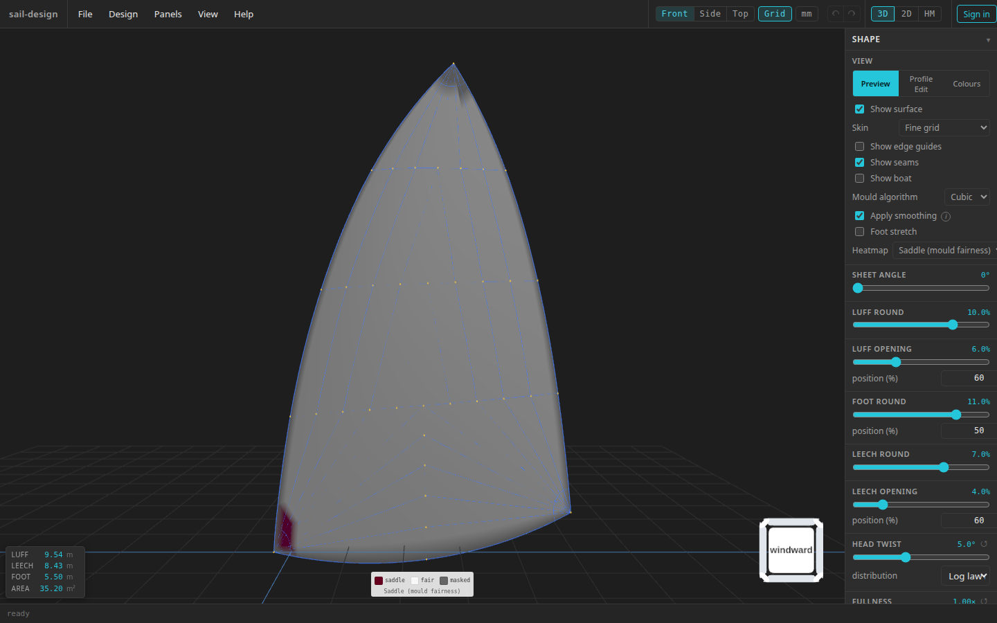
The lightweight overlay keeps the normal Preview controls and shows one wind-independent, non-cross-cut field.
- Saddle overlay on the live mould
- Categorical saddle, fair, and masked legend
- Heatmap selector in the Shape card
Pressure, Stretch energy, and the three cross-cut fields are not offered in this selector. They need controls or context that only the dedicated workspace provides.
Compare fields in the HM workspace
Open HM
Click HM in the canvas switch, or choose View > Heatmap. With no saved selection, the workspace starts with K and H.
Choose two or three chips
Click an unselected chip to add it. Click a selected chip to remove it, unless only two remain. If three are already selected, adding another drops the chip that has been selected longest and adds the new one. The counter reports
2 / 3or3 / 3.All eight chips are currently enabled. The selection is restored after a reload and when you leave HM and return.
Move the linked camera
Left-drag to orbit, middle-drag or Space+left-drag to pan, and use the wheel to zoom towards the pointer. A gesture over any tile moves every selected tile to the same viewpoint, so their surface regions stay aligned.
See 3-D preview for the complete camera behavior.
Within one visit, wind values remain in place if the selected fields make the wind controls disappear and reappear. Leaving HM rebuilds the workspace; the next visit starts with a newly framed camera, TWS 12 kn, and AWA 0°, while the chosen chips remain.
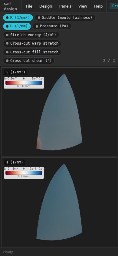
At a portrait viewport, the picker wraps and selected tiles stack. The current application top bar remains wider than this 390 px view, so controls outside the crop require horizontal scrolling.
Read the legends
The title and tick labels on each tile define how to read its colours. Red is not a universal warning and blue is not a universal pass state.
| Legend mode | Current fields | Colour meaning |
|---|---|---|
| Signed | K, H, cross-cut warp, fill, and shear | Red is negative, near-white is zero, and blue is positive. K and H use fixed signed-log scales; the cross-cut fields use fixed signed clips. |
| Linear | Pressure and Stretch energy | Near-white is zero and blue approaches the upper clip. Pressure's upper tick changes with TWS. |
| Categorical | Saddle | Separate swatches label saddle, fair, and masked; it is not a continuous scale. |
Grey is a sentinel rather than zero:
- Saddle masks the one-cell boundary ring, degenerate cells, and the near-singular head collar so those regions are not classified as saddle.
- Stretch energy is grey where K is zero or negative, because its membrane calculation is undefined there.
- Cross-cut warp and fill use grey where K is zero or negative, and for any point without finite grain coverage. Shear remains defined on a saddle when its grain demand is finite; a non-finite grain value is also coloured grey, although the current shear legend has no grey key.
If an entire required input is unavailable, the selected chip and counter stay visible but that field's tile is omitted; blank grid space can remain. The current workspace does not show a separate unavailable message.
Compare all eight fields
Every entry below is currently ready and selectable. “Overlay” means the single-field selector in Preview and Profile Edit; “HM” means the linked-tile workspace.
| Field | Scale | Surface | Depends on | What the colour represents |
|---|---|---|---|---|
| K (Gaussian curvature) | 1/mm², signed log | Overlay + HM | Current mould curvature; no wind or cloth input | Negative, zero, or positive Gaussian curvature: saddle-like, developable/flat, or cap-like surface type |
| Saddle (mould fairness) | Categorical | Overlay + HM | K plus the current mould's positive-curvature reference and mask | Red only below the per-mould saddle cut, near-white where fair, and grey where masked |
| H (mean curvature) | 1/mm, signed log | Overlay + HM | Current mould curvature; no wind or cloth input | Signed mean bend relative to the surface normal |
| Pressure | Pa, linear | HM only | Surface normals, TWS, and AWA; no cloth input | Modelled pressure on the windward face, from zero to the current TWS ceiling |
| Stretch energy | J/m², linear to 1.00+ | HM only | K and modelled pressure; one fixed nominal membrane stiffness | Modelled elastic energy density; grey where K ≤ 0 |
| Cross-cut warp stretch | Ratio, signed ticks at −10%, 0, +10% | HM only | Cross-cut grain demand, cloth stretch profile, K, normals, TWS, and AWA | Geometric and wind-driven stretch resolved along warp |
| Cross-cut fill stretch | Ratio, signed ticks at −10%, 0, +10% | HM only | The same inputs as warp | Geometric and wind-driven stretch resolved along fill |
| Cross-cut shear | Degrees, signed ticks at −30°, 0, +30° | HM only | Cross-cut grain demand and cloth stretch profile; no wind | Accumulated grain-skew demand from the cross-cut grain origin |
Exact Saddle classification
The current classifier takes the median positive K over the unmasked mould interior as its reference. An unmasked point is labelled saddle only when its K is below −0.4 × that reference. A mildly negative K can therefore still be labelled fair. The separate K field shows the continuous signed value.
The general Stretch energy field does not use the stretch profile from Cloth Properties. It uses one fixed nominal stiffness of 50,000 N/m. The three cross-cut fields do use the current Stretch profile, or the profile derived from Material when Stretch profile is Auto (from material).
Set wind-dependent fields
The wind strip appears whenever at least one selected field is Pressure, Stretch energy, Cross-cut warp stretch, or Cross-cut fill stretch. It hides when every selected field ignores wind.
| Control | Range | Step | Initial value |
|---|---|---|---|
| TWS (true wind speed) | 0–50 kn | 1 kn | 12 kn |
| AWA (apparent wind angle) | −90°–+90° | 5° | 0° |
Changing either slider recolours the dependent tiles immediately; there is no Solve or Apply action. K, Saddle, H, and Cross-cut shear do not change with these sliders. Pressure's legend ceiling changes with TWS, so the same shade at two wind speeds does not mean the same number of pascals.
Understand the cross-cut context
The cross-cut labels describe a generated grain lattice used by these three diagnostics. That context exists only in HM, which is why the fields do not appear in the lightweight overlay.
The current app generates this context from the live mould and cross-cut construction settings even when the selected panel layout is not Cross-cut. The following controlled capture still has the Albin Vega 27 gennaker's Tri-radial layout selected; all three fields render. Changing the panel layout to Cross-cut is therefore not a current availability gate.
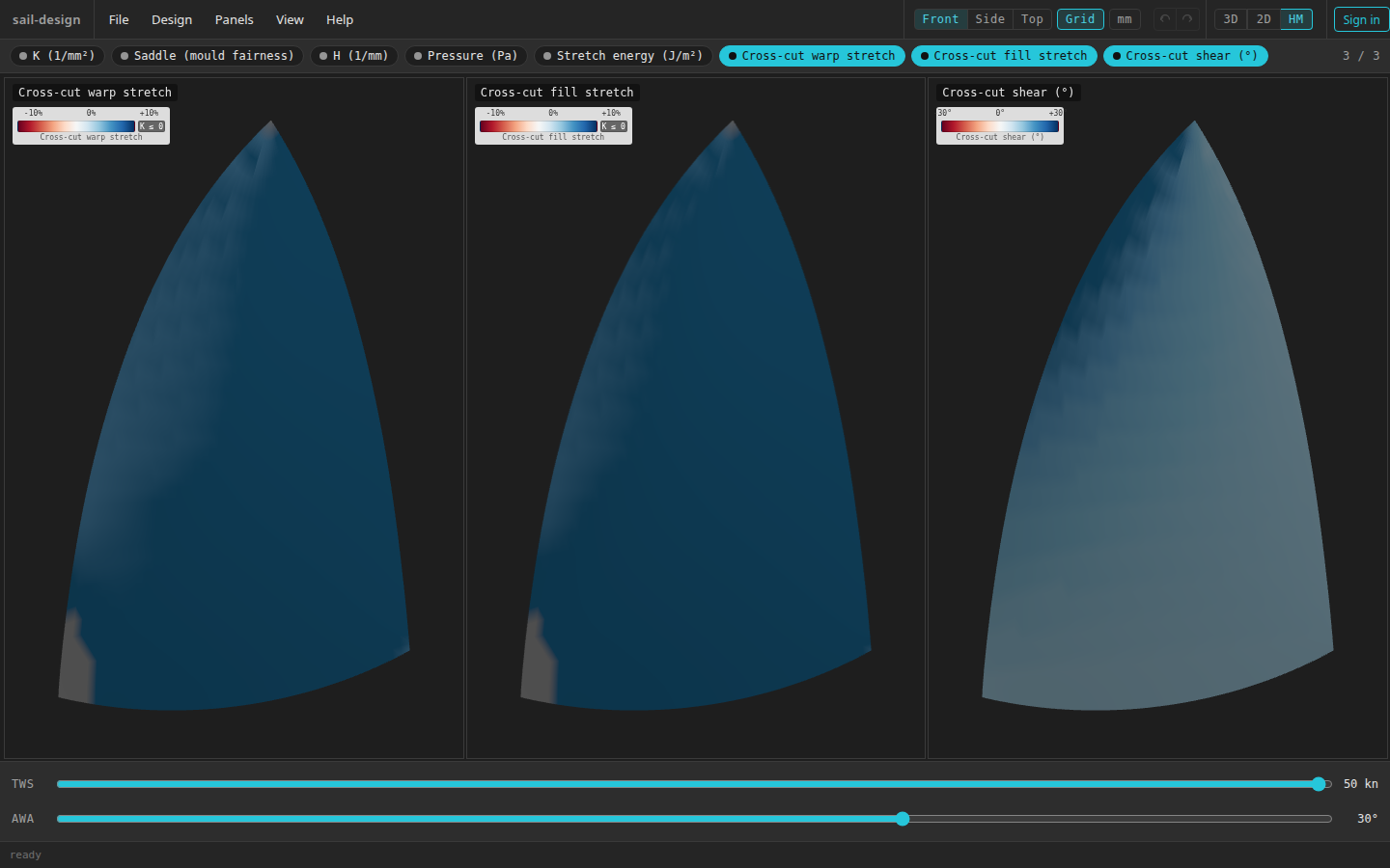
A controlled Tri-radial design state with the three generated cross-cut diagnostics, at TWS 50 kn and AWA 30°.
- Three selected cross-cut fields
- Signed legends and K ≤ 0 key
- Grey sentinel on warp and fill
- Wind controls affect warp and fill, not shear
Warp and fill combine the accumulated geometric demand with a wind-driven elastic term. Shear uses the accumulated geometric demand and ignores wind. The cloth stretch profile controls how that demand is divided among shear, warp, and fill, so a cloth change can recolour all three.
These fields are read-only diagnostics. The app does not attach a pass/fail threshold, recommend a shape change, or turn a colour region directly into a panel or reinforcement dimension.