Corner Patches DXF
Download the current tack, head, and clew reinforcement patterns in a patch-only CAD file.
Download the patch file
Choose File > Export > Corner Patches DXF. This action is not present in the panel-viewer toolbar, and it has no options dialog. The browser downloads patches.dxf.
If none of the configured corner radii produces a usable layer, the app shows an error instead of downloading an empty file.
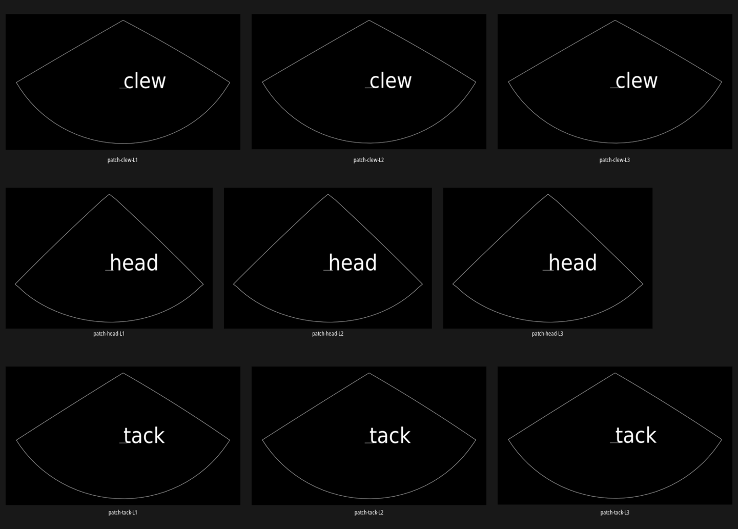
The Albin Vega 27 gennaker example with levels 1–3 enabled at all three corners; each frame shows one isolated DXF layer.
- Clew row
- Head row
- Tack row
- Levels 1–3 run left to right
Read the layers
The file is a 1:1 millimetre DXF. Each enabled level has a layer named for its corner and level, such as patch-tack-L1. A layer contains the closed patch boundary, a warp-direction line, and a corner-name label.
The patch shapes use their own local coordinates. Showing all layers at once makes the tack, head, and clew shapes overlap; isolate one layer to see its actual outline. These layers do not contain seam-allowance lines, panel seam labels, or roll nesting.
Verify each pattern
Isolate one corner and level
Turn off the other layers. Confirm that the layer name identifies the intended corner and level.
Check the nested sizes
Compare the available levels at one corner. The successive patch boundaries should form a nested set; a radius below 50 mm is omitted from the export.
Confirm millimetres and warp direction
Open the DXF without rescaling, measure a known dimension, and identify the straight warp mark before arranging the pattern on material.
Verify before cutting
The DXF has no calibration rectangle and no added allowance. Check the CAD measurement and downstream output before using the boundary as a pattern.