Corner patches
Set the reinforcement outline at each sail corner and control how the exported patch layers step inward.
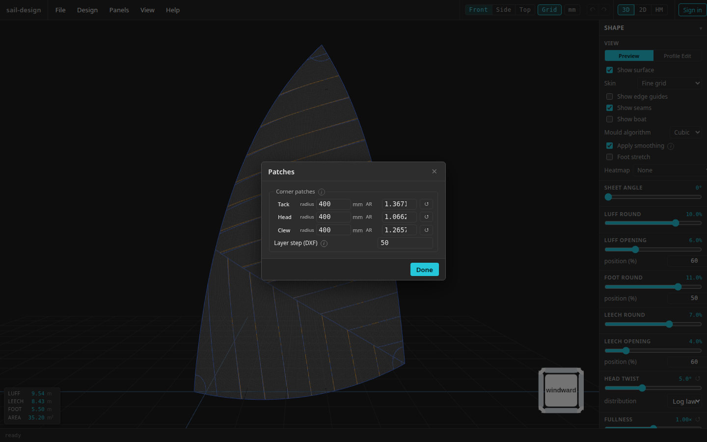
The blue corner arcs behind the dialog are the live outer outlines; inner export layers are not drawn in the 3-D preview.
- Per-corner radius and aspect ratio
- DXF layer step
- Live outer patch outline
Shape each corner outline
The dialog has one row for Tack, Head, and Clew.
| Control | Current range and effect |
|---|---|
| radius | The displayed range is 50–2,000 mm. It sets how far the outer patch reaches along the longer of the two adjacent sail edges. |
| AR | 1.0–3.0. The shorter-edge reach is the radius divided by this value; 1.0 gives equal reach along both edges. |
| ↺ | Resets that corner's aspect ratio to 1.0. |
A fresh design starts with aspect ratios calculated from the current mould's adjacent edge lengths. That is why the three initial values may differ even when their radii are equal.
Set the tack, head, and clew radii
Change one radius at a time and watch the corresponding blue arc move on the 3-D sail.
Checkpoint
The outer outline updates without generating panels or contacting the backend.
Adjust the aspect ratios
Increase AR to shorten the outline along one adjacent edge while retaining the entered main radius along the other. Use ↺ when you want equal reach.
Set the export layer step
Set Layer step (DXF) from 10 to 200 mm. The export starts with the visible outer radius, then attempts two smaller layers by subtracting this value once and twice.
Keep the changes
Select Done. Patch values are included when you save the design.
Preview versus exported layers
The 3-D workspace draws only the outer outline for each corner. Corner Patches DXF can contain up to three flattened layers per corner:
- the entered main radius;
- main radius minus one layer step; and
- main radius minus two layer steps.
Any calculated layer below 50 mm is omitted. For example, an 80 mm patch with a 50 mm step exports only the 80 mm outer layer.
The radius input currently accepts a typed positive value below its displayed 50 mm minimum, but the export's 50 mm layer floor still applies. Use at least 50 mm when you expect that corner to appear in the file.
Patch layers have no panel seam neighbours and receive no seam allowance. The Corner Patches DXF guide covers the file, sign-in requirement, and rendered checks. Unlike the panel exports, this action does not require Generate Panels first.